01 SYSTEM 02 FIELD TESTING 03 MCHS 04 ROADMAP 05 DOCUMENTATION 06 TEAM
ILE ALATAU · KAZAKHSTAN

BEYOND CELLULAR COVERAGE.

Alpine Rescue System is an offline-capable mountain safety platform combining GNSS positioning, LoRa telemetry, emergency signalling and rescue coordination for environments where conventional connectivity cannot be relied upon.

FIELD REGION 43° N · 77° E
SYSTEM Field Prototype
RADIO LoRa 868 MHz
POSITIONING GNSS / GPS
OPERATION Offline-Capable
SCROLL TO EXPLORE
PROJECT ORIGIN · ILE ALATAU

The project began with uncertainty in the mountains.

Alpine Rescue System was not conceived as a theoretical classroom exercise. The engineering problem emerged from direct experience of a long mountain journey where distance, time, terrain and limited communications made situational awareness increasingly important.

The resulting question was deliberately narrow: could a low-cost GPS and LoRa prototype provide rescuers with additional structured information — trip context, last-known position and an explicit emergency state — when continuous mobile coverage could not be assumed?

38 KM

Project-origin journey

26 H

Continuous effort

4,147 M

Molodezhny Peak

1 DATA CHAIN

Registration → telemetry → dashboard

ENGINEERING RESPONSE

ARS does not attempt to replace certified rescue equipment. It investigates whether a GPS/LoRa MVP can provide additional situational information and support earlier, better-informed decisions.

01 · THE PROBLEM

When the signal disappears, so can the last known position.

Mountain groups can move into terrain where cellular coverage becomes unreliable or unavailable. When a group becomes overdue, injured or lost, rescuers may have little recent information about its position, movement history or operational status.

01 Connectivity Gaps

Valleys, terrain obstacles and remote routes can interrupt conventional mobile coverage.

02 Unknown Position

Without recent telemetry, rescuers may lack a reliable final latitude, longitude or altitude.

03 Delayed Escalation

A missed return time provides limited context when there is no active status or emergency signal.

02 · SYSTEM ARCHITECTURE

Two data paths. One operator view.

Alpine Rescue System separates trip registration from radio telemetry. The tourist creates journey context before departure, while the beacon independently transmits live field data. Both streams are joined later in the backend.

REGISTRATION PATH

Creates identity and route context before departure.

01 TOURIST

Scan Device QR

Opens the registration page associated with the selected beacon.

02 TRIP FORM

Register Journey

Route, leader, group size, expected return and emergency contact.

03 API

POST /trips

The backend validates and stores the new active journey.

04 RECORD

Trip Context

Stores deviceId, tripId, route intention and return-time context.

TELEMETRY PATH

Carries live device evidence independently of the QR workflow.

01 BEACON

T-Beam Beacon

GPS position, altitude, satellites, battery, status and SOS.

02 RADIO

868 MHz LoRa

Compact telemetry transmitted without cellular connectivity.

03 RECEIVER

T-Beam Gateway

Receives the radio packet and measures RSSI and SNR.

04 SERIAL

USB Bridge

Forwards structured telemetry to the local backend.

BACKEND JOIN

deviceId + tripId

TRIP CONTEXT Identity · Route · Return Time
+
LATEST TELEMETRY Position · Battery · SOS
+
RECEIVER DATA RSSI · SNR · Timestamp
OPERATOR OUTPUT

Rescue Dashboard

One operator view combines who is on the route, where the beacon was last seen, packet freshness, battery state, overdue status and emergency alerts.

OPEN DASHBOARD ↗
ARB-001 SAFE
LAT / LON 43.08 / 77.08
BATTERY 76%
RSSI -61 dBm
ALERT NONE
ARCHITECTURE PRINCIPLE

QR registration does not pass through the beacon or LoRa receiver. It writes trip context directly to the backend. Radio telemetry follows a separate path and is joined later using device and trip identity.

03 · THE DEVICE

One integrated platform. Built to remain inspectable.

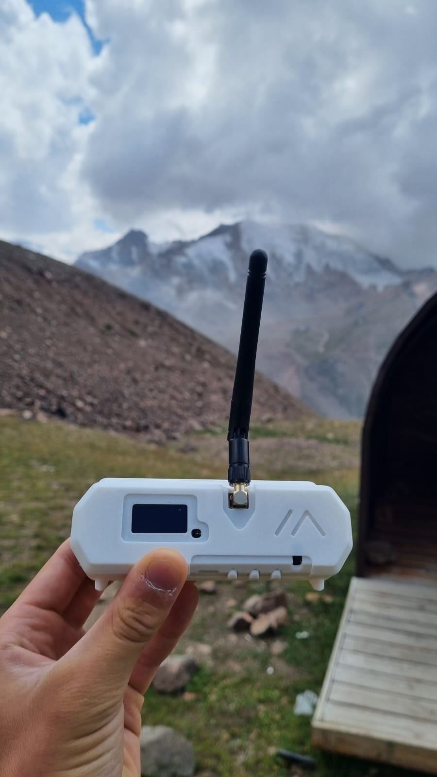
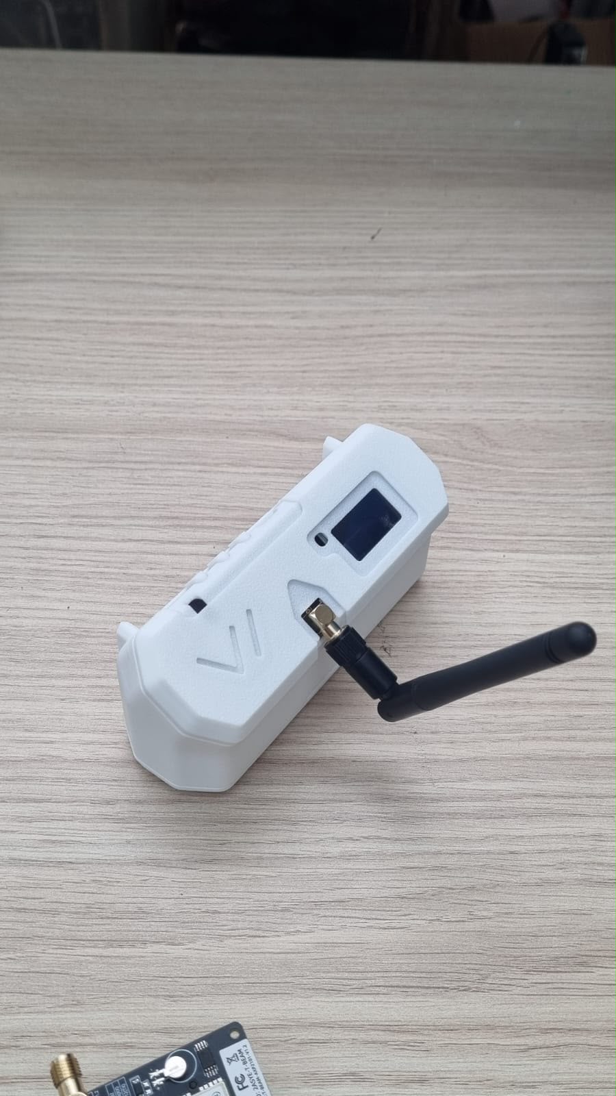
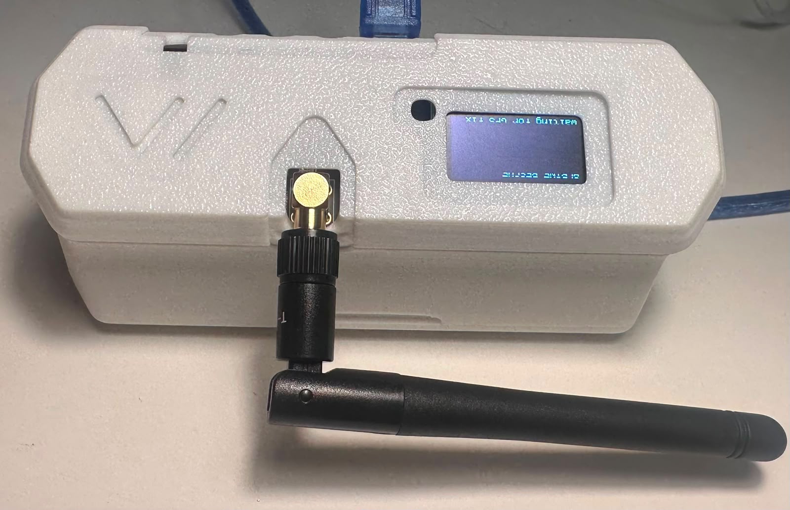
The field prototype is built around the LilyGO T-Beam AXP2101 V1.2 platform. GNSS, LoRa communication, local status, battery support and the primary SOS input are integrated into one serviceable package rather than distributed across multiple external modules.

Alpine Rescue System ARB field prototype
FIELD PROTOTYPE ARB-001
01
POSITIONING Integrated GNSS

u-blox positioning provides latitude, longitude, altitude, satellite count and fix information.

02
RADIO LoRa · 868 MHz

Point-to-point telemetry is transmitted to a second matched T-Beam receiver without a cellular link.

03
LOCAL INTERFACE OLED Display

Provides local GPS, battery, state and SOS information without requiring a phone or internet connection.

04
EMERGENCY INPUT 5 s SOS Hold

The onboard button uses a deliberate approximately five-second hold to reduce accidental activation.

PLATFORM LilyGO T-Beam AXP2101 V1.2
CONTROLLER ESP32 Embedded firmware
RADIO 868 MHz LoRa telemetry
POSITION u-blox Integrated GNSS
POWER 18650 Protected Li-ion
CONTROL GPIO 38 Onboard SOS
DESIGN PRINCIPLE

Integrated before customised.

The MVP deliberately uses integrated, inspectable and replaceable hardware until field evidence justifies custom electronics or a production enclosure.

CURRENT REVISION V1.2 / FIELD MVP
04 · DESIGN EVOLUTION

Every revision removed a real failure point.

The enclosure was not treated as decoration. Each iteration responded to fit, access, antenna loading, battery depth, display visibility or durability risk.

01
EARLY CONCEPT

Initial enclosure geometry

The first housing established the overall handheld form, OLED position, antenna clearance and basic internal packaging.

02
V6

Fit becomes engineering

Battery depth, side-wall geometry, OLED opening and antenna orientation were refined around the real T-Beam assembly.

OLED OPENING Visibility + protection
BATTERY DEPTH Match real 18650 packaging
ANTENNA / SMA Reduce bending load
BUTTON ACCESS Retain onboard SOS
MOUNTING Carry / attachment geometry
ENGINEERING DECISION
REMOVED

External status LED

Bench testing showed that the external LED duplicated information already available on the OLED and dashboard while adding solder joints, separate wiring and another enclosure vulnerability.

RESULT Cleaner assembly Fewer failure points Better enclosure integrity
08 · FIELD VALIDATION

From rescue base to high-altitude terrain.

ILE ALATAU · ALMATY

The prototype was tested progressively across six field stations with changing altitude, terrain, obstruction and radio geometry.

ST00
BASELINE

MCHS Base

Initial system verification before moving into progressively more difficult terrain.

ALTITUDE 2,264 m
ST01
VEGETATION

Forest Section

Radio behaviour was observed with increased vegetation and partial obstruction.

ENVIRONMENT FOREST
ST02
ROUTE TRANSITION

River / Open Route

A transition point between lower terrain and the higher mountain route.

PACKETS 30 / 30
ST03
MYNZHYLKY

High Mountain Station

Mynzhylky became an important reference point for higher-altitude and longer-separation testing.

RADIO SEPARATION 2,205 m
ST04
OBSTRUCTION

Terrain Shadow

Mountain geometry introduced a more difficult radio path and non-line-of-sight conditions.

CONDITION SHADOWED
ST05
ALPININGRAD

Maximum Recorded Separation

The highest and longest recorded test station in the validation programme.

SEPARATION 4,180 m
STATIONS 6 Progressive field points
MAX ALTITUDE 3,604 m Recorded during programme
MAX SEPARATION 4,180 m Recorded, not certified range
ENVIRONMENT REAL TERRAIN Vegetation · shadow · altitude
VIEW MEASURED RESULTS
09 · PRE-TRIP REGISTRATION

Every beacon begins with a declared journey.

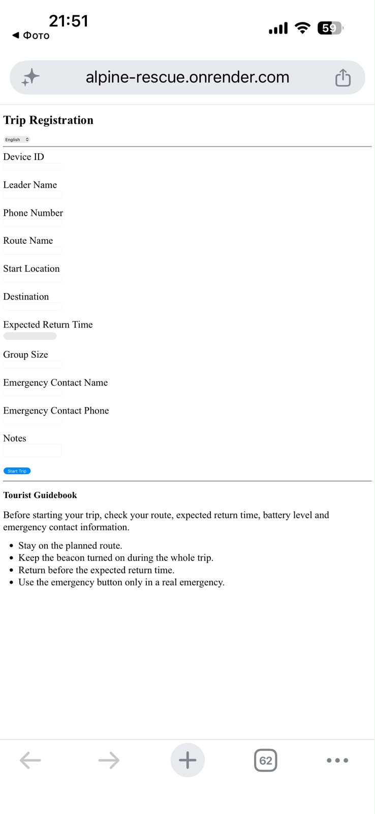
Before departure, the device QR links one physical beacon to one active trip record. This creates the identity, route and expected-return context that later gives incoming telemetry operational meaning.

ARS trip registration page on a mobile device
MOBILE ENTRY POINT Device-specific QR
01
IDENTIFY

Scan device QR

The QR identifies the selected beacon and opens the registration page for that device.

02
REGISTER

Declare the journey

The group leader enters route, contacts, group size and expected return time.

03
CREATE

POST /trips

The backend creates the active trip record and stores the journey context.

04
LINK

deviceId + tripId

Future telemetry can now be interpreted as data belonging to a specific active journey.

TRIP RECORD

Context before telemetry.

DEVICE deviceId
LEADER leaderName
CONTACT phone
ROUTE routeName
START startLocation
END endLocation
RETURN expectedReturnTime
GROUP groupSize
EMERGENCY emergencyContact
START TIME startTime
ARCHITECTURE BOUNDARY

QR registration writes directly to the backend. It does not pass through the beacon or LoRa receiver. The beacon carries device identity; the backend stores journey context.

10 · OPERATOR INTERFACE

Telemetry becomes operational context.

LOCAL RESCUE INTERFACE

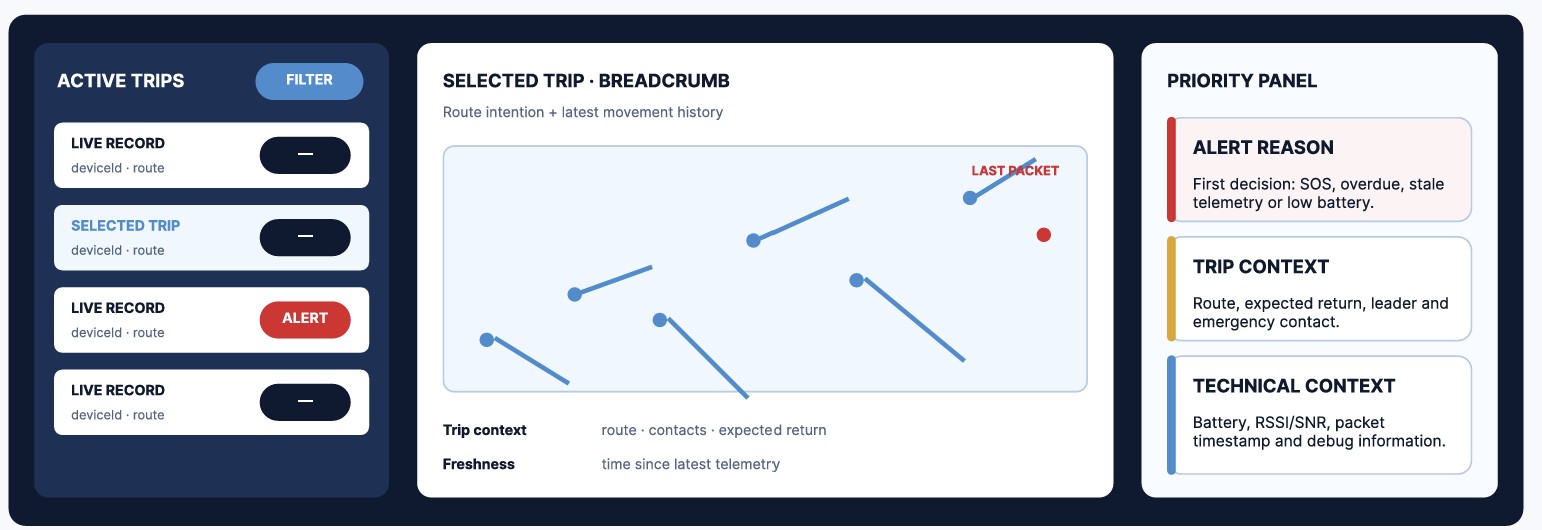
The dashboard combines active-trip information, incoming telemetry, position history and alert state into one operator-facing interface.

localhost:3000/dashboard
LOCAL
ARS local rescue operator dashboard
OPERATOR VIEW

The interface is designed around one question: what does the rescue operator need to understand immediately?

INFORMATION HIERARCHY

Signal first. Noise second.

01
+
IDENTITY

Active Trip

Device ID, group leader, route and expected return context identify the journey being monitored.

02
POSITION

Current Location

The latest GNSS coordinates place the beacon on the local map.

03
HISTORY

Breadcrumb Trail

Historical telemetry points preserve recent movement rather than showing only one marker.

04
%
DEVICE

Battery State

Reported battery percentage gives the operator additional device-health context.

05
RADIO

RSSI + SNR

Radio diagnostics are available for engineering and field-link assessment.

06
!
PRIORITY

Alert Reason

The interface should explain why attention is required rather than displaying colour alone.

OPERATOR WORKFLOW

One packet. Five decisions.

01 RECEIVE

New telemetry enters the backend.

02 IDENTIFY

Match device to active trip.

03 LOCATE

Update map and breadcrumb history.

04 ASSESS

Review time, battery and alert state.

05 PRIORITISE

Surface trips requiring operator attention.

TELEMETRY OBJECT

What reaches the interface.

The backend converts received serial data into structured telemetry records that can be stored, filtered and visualised.

ARB-001 ● RECEIVED
deviceId "ARB-001"
latitude 43.0...
longitude 77.0...
altitude 3604 m
satellites 8
battery 87%
emergency false
timestamp local record
HUMAN FACTOR

A rescue interface should reduce interpretation, not add to it.

The dashboard therefore prioritises location, journey state, alert reason and telemetry freshness over decorative information.

11 · ENGINEERING EVOLUTION

From bench uncertainty to a field-tested system.

ARS did not move directly from idea to finished device. The project progressed through subsystem isolation, mechanical iteration, integration and field validation.

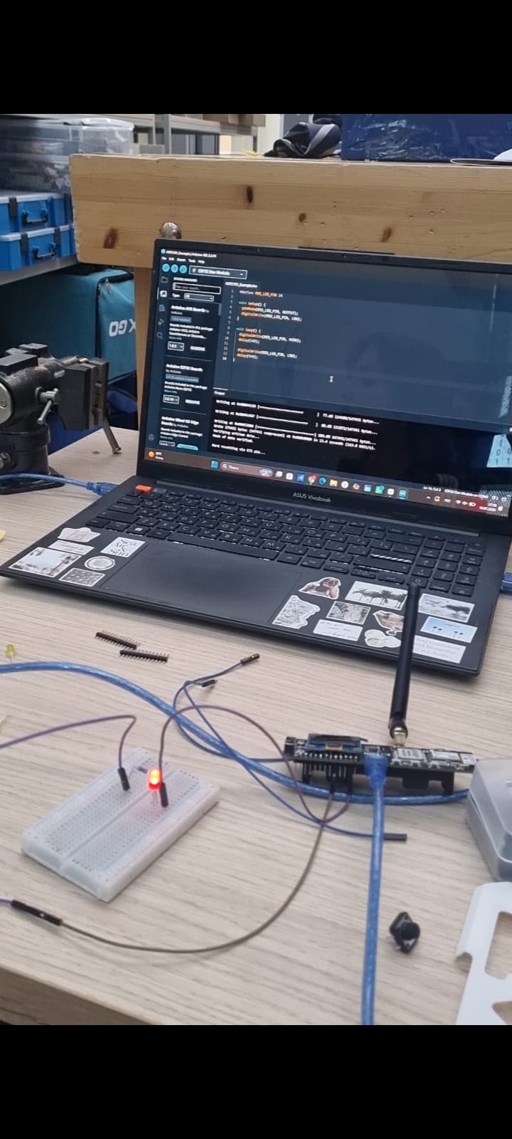
ARS early bench integration and electronics development
01 / BENCH
INTEGRATION

First make each subsystem work.

Early development focused on reducing simultaneous unknowns: power startup, OLED output, GPS fix acquisition, LoRa matching and firmware upload were verified before the full system was assembled.

POWER AXP2101 / ALDO3
GNSS VALID FIX
RADIO MATCHED LORA
SUBSYSTEMS VERIFIED
ARS enclosure development and manufacturing process
02 / BUILD
MECHANICAL ITERATION

Packaging became part of the engineering.

The enclosure was revised around real fit, battery depth, OLED visibility, SMA loading, button access and serviceability.

ENCLOSURE V6 → V7
MANUFACTURING FDM
PLATFORM BAMBU X1-C
FIT + FUNCTION VERIFIED
ARS final integrated field prototype
03 / FIELD MVP
INTEGRATED PROTOTYPE

One complete data chain.

The final MVP combines the T-Beam platform, GNSS, 868 MHz LoRa, OLED interface, onboard SOS, protected 18650 power, QR identity and the serviceable enclosure into one field-testable system.

STATUS FIELD TESTED
STATIONS 6 / 6
MAX SEPARATION 4,180 m
DECISION LOG

What changed — and why.

D01 Enable ALDO3 before peripheral startup

Required by the final AXP2101 board revision for stable GPS/OLED operation.

D02 Test LoRa before backend integration

Radio settings were isolated first so communication faults were easier to diagnose.

D03 Remove external LED

OLED and dashboard already supplied the information while the LED added wiring and enclosure risk.

D04 Iterate enclosure around actual hardware

Battery depth, antenna loading, OLED opening and button access required physical fit revisions.

ENGINEERING METHOD
OBSERVE ISOLATE CHANGE RETEST RECORD
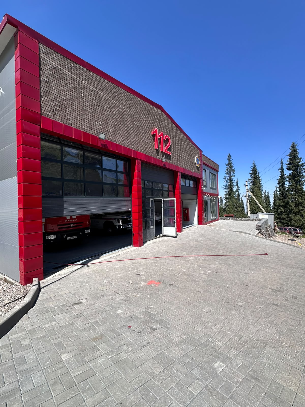
ARS field stakeholder evaluation context at MCHS base
FIELD STAKEHOLDER CONTEXT MCHS · 112
12 · STAKEHOLDER EVALUATION

Feedback becomes the next engineering requirement.

Field evaluation was used to identify what information is immediately useful to rescue personnel, what remains operationally weak and what should be changed before any controlled pilot.

MOST USEFUL Location + current condition

GPS position and a clear SOS state were identified as highly useful operator information.

PRIMARY CONCERN Enclosure strength

Mechanical robustness remains one of the main barriers before a controlled operational pilot.

UX CONCERN Alert ambiguity

Yellow status should communicate the exact warning reason instead of requiring interpretation from colour alone.

FUTURE TARGET ~15 km

The approximately 15 km figure is a stakeholder-informed future validation target. It is not a demonstrated ARS range. The current field-tested maximum recorded separation remains 4,180 m.

PROJECT PRINCIPLE

External feedback is not validation by itself.

Feedback becomes engineering evidence only when it is translated into a requirement, prioritised, implemented and retested.

13 · DEVELOPMENT ROADMAP

Stabilise first. Pilot second.

Future development is gated by field evidence. The next version should not add features for appearance; it should close the weaknesses already identified during engineering review and mountain validation.

PHASE 01 NEXT
MVP STABILISATION

Make the evidence repeatable.

Close the remaining technical weaknesses before increasing operational complexity.

01 Firmware reliability
02 Verified receiver bridge
03 Antenna placement
04 Enclosure sealing
05 Full battery measurement
PHASE 02 CONTROLLED
CONTROLLED PILOT

Test the operating model.

Only after the MVP is stable should the project test a more realistic multi-user rescue workflow.

01 Custom PCB study
02 Authenticated backend
03 Structured database
04 Multiple receivers
05 MCHS procedures
PHASE 03 CONCEPT
DEPLOYMENT CONCEPT

Design the service around the device.

Deployment requires much more than hardware. Issue, charging, inspection, training and maintenance become part of the system.

01 Rental / issue workflow
02 Charging + inspection
03 Operator training
04 Maintenance records
05 Controlled route coverage
ENGINEERING GATES

Progress is earned, not scheduled.

Each next phase is conditional on specific technical and operational evidence.

GATE A

Evidence reconciled

No unresolved numerical conflict in the validation dataset.

REQUIRED
GATE B

Critical failures controlled

Retesting demonstrates repeatable improvement in weak subsystems.

REQUIRED
GATE C

Operational workflow approved

Roles, alerts and escalation procedures are understood.

PILOT GATE
GATE D

Production risks reviewed

Power, enclosure, security and maintenance risks are evaluated.

DEPLOYMENT GATE
NEXT VALIDATION CYCLE

The next questions are already known.

EVIDENCE Automatic raw logging

Save telemetry and Serial records with synchronised timestamps and station IDs.

RADIO Repeat controlled conditions

Separate line-of-sight, partial obstruction and terrain-shadow trials.

GPS Independent reference

Measure actual horizontal error, fix time and reacquisition rather than satellite count alone.

BATTERY Full-charge endurance

Run from known full charge to shutdown while recording voltage, percentage and temperature.

SOS One synchronised evidence chain

Record button hold, OLED state, emergency packet and dashboard transition together.

NETWORK Multi-receiver study

Evaluate whether additional receivers improve terrain-shadow resilience.

NEXT PROTOTYPE DIRECTION

Evidence before complexity.

ENCLOSURE SEALING ANTENNA PLACEMENT AUTHENTICATED BACKEND MULTI-RECEIVER
DEVELOPMENT BOUNDARY

ARS remains an experimental engineering prototype until repeatable testing, operational approval and production safety controls are completed.

14 · DOCUMENTATION & ACCESS

One project. Multiple ways to enter it.

Technical evidence, enterprise planning and multilingual executive summaries are organised as direct project resources.

01 TECHNICAL
ENGINEERING PORTFOLIO

Full technical development record.

Hardware architecture, firmware, CAD, enclosure iteration, field validation, failures, engineering decisions and results.

OPEN ENGINEERING PORTFOLIO
02 ENTERPRISE
ENTERPRISE PORTFOLIO

Commercial and deployment strategy.

Market logic, stakeholder value, economics, deployment model, pricing assumptions and future operational structure.

OPEN ENTERPRISE PORTFOLIO
03 EXECUTIVE SUMMARY

Executive Summary

Select the language in which you would like to read the ARS executive project summary.

SELECTED LANGUAGE English
READ IN ENGLISH
05 · FIELD VALIDATION

Tested in real terrain. Measured, not assumed.

NUMERICAL BASELINE RESULTS_FREEZE_v1
MAX RECORDED SEPARATION FIELD VERIFIED
4,180 m
ST05 · ALPININGRAD 30 / 30 PACKETS
AGGREGATE PACKET DELIVERY VERIFIED
93.9 %
180 SENT 169 RECEIVED
01 FIELD STATIONS 6 / 6

All recorded station outcomes were marked PASS.

02 MAX TEST ALTITUDE 3,604 m

Highest recorded station reading at ST05.

03 GPS AVAILABILITY 4–8

Satellites recorded across ST00–ST05.

04 ENDURANCE TEST 7 h

Separate run from 34% indicated charge to 0%.

PACKET DELIVERY BY STATION

Range alone did not determine performance.

Packet delivery varied with terrain, obstruction, antenna orientation and local geometry rather than decreasing monotonically with separation.

ST00 Baseline
100%
ST01 Lower Route
86.7%
ST02 Open Route
100%
ST03 Mynzhylky
83.3%
ST04 Terrain Shadow
93.3%
ST05 Alpiningrad
100%
WHAT WORKED

End-to-end operation

GPS remained available at every station. The telemetry pipeline operated from beacon through LoRa receiver, USB Serial, backend ingestion and dashboard monitoring.

WHAT DEGRADED

Packet delivery

ST03 recorded the highest station-level packet loss at 16.7%. Shorter and longer test points sometimes achieved 100%, showing that distance alone is not a sufficient model of radio performance.

WHAT CHANGES NEXT

Stronger evidence

Future work requires repeated controlled range trials, reconciled raw Serial and telemetry logs, improved attachment protection and a full 100%-to-shutdown battery test if total runtime is to be claimed.

ENGINEERING CLAIM DISCIPLINE

Targets are not results.

The 4,180 m figure is the maximum recorded separation in this field programme, not a certified maximum range. GPS availability does not establish metre-level positional accuracy. The endurance test does not establish a complete full-pack runtime from 100%.

06 · SAFETY STATE LOGIC

Status is not binary. Context changes before emergency.

ARS uses a three-state operating model to separate normal operation, developing concern and explicit emergency conditions. The purpose is to give the operator more context than a simple online/offline indicator.

GREEN
01

Normal operation

The group is within expected operating conditions and no emergency state has been detected.

TRIP STATUS ACTIVE
SOS INACTIVE
TELEMETRY RECEIVING
CONDITIONS CHANGE
YELLOW
02

Attention required

Something requires operator attention, but the system has not entered an explicit emergency condition.

EXAMPLE OVERDUE
EXAMPLE LOW BATTERY
EXAMPLE STALE DATA
EMERGENCY TRIGGER
RED
03

Emergency state

A direct SOS trigger or explicit emergency condition moves the system into the highest-priority operator state.

PRIORITY CRITICAL
DASHBOARD ALERT
DEVICE SOS ACTIVE
MANUAL EMERGENCY INPUT

Hold for five seconds.

The onboard button requires a deliberate hold before an SOS is accepted. The delay is intended to reduce accidental activation during normal handling or transport.

01 BUTTON PRESS Input begins
02 5.0 s Hold threshold
03 SOS ACTIVE Device state
04 RED ALERT Operator view
OPERATOR PRINCIPLE

Show the reason, not just the colour.

YELLOW OVERDUE

Expected return time has passed.

YELLOW LOW BATTERY

Device power requires operator attention.

YELLOW STALE TELEMETRY

No sufficiently recent packet has been received.

RED SOS

Explicit emergency input has been activated.

MVP SAFETY LIMIT

State classification is an operator-support mechanism within the prototype. It is not a certified emergency classification standard and should not replace established rescue procedures.

07 · OFFLINE ARCHITECTURE

No cloud required. No cellular network required.

The critical operational chain is designed to remain available locally. Positioning, radio telemetry, serial transfer, backend processing, map rendering and storage can all operate without a live internet connection.

01
POSITIONING

GNSS / GPS

Satellite positioning is independent of mobile data.

OFFLINE
02
RADIO LINK

LoRa 868 MHz

Beacon-to-receiver telemetry uses direct radio communication.

OFFLINE
03
SERIAL BRIDGE

USB / COM Port

Receiver data is passed directly into the local laptop.

LOCAL
04
BACKEND

Node.js + Express

Trips, telemetry and events are processed on localhost.

LOCALHOST
05
MAPPING

Leaflet + PMTiles

Regional map data is stored locally for field use.

OFFLINE MAP
06
STORAGE

Local JSON Database

Trip and telemetry history remain available on the laptop.

LOCAL
INTERNET ROLE

Useful, but not critical.

INTERNET AVAILABLE Remote access

Hosted dashboard, remote stakeholders and online services.

INTERNET UNAVAILABLE Local rescue workflow

Beacon, receiver, backend, storage and maps continue locally.

CRITICAL PATH

The field data path stays local.

01 GNSS
02 BEACON
03 LORA
04 RECEIVER
05 USB
06 BACKEND
07 DASHBOARD
SYSTEM PRINCIPLE

Internet should improve the system, not define whether it exists.

The MVP is designed so that internet access can add convenience and remote visibility, while the core field workflow remains functional on a local laptop.

03 · LIVE TELEMETRY

Engineering data, translated into rescue visibility.

The beacon transmits the data required to understand where the group is, whether the device is healthy and whether an emergency state has been activated.

OPEN RESCUE DASHBOARD ↗
DEVICE ARB-001
SAFE
LATITUDE 43.08512°
LONGITUDE 77.07946°
ALTITUDE 3,012 m
SATELLITES 9
BATTERY 76%
RSSI -61 dBm
SNR 9.8 dB
SOS INACTIVE
04 · FIELD TESTING

Built for the mountains. Tested in them.

Field testing takes place in the Ile Alatau mountain environment around Almaty.

01 Medeu
02 Shymbulak
03 Mynzhylky
05 · ENGINEERING

Not one device. One integrated system.

01

Embedded Firmware

GPS acquisition, LoRa transmission, SOS logic, battery monitoring and OLED interface.

02

Radio Communication

868 MHz LoRa packets with signal strength, SNR and telemetry delivery testing.

03

Backend

Node.js and Express backend with local telemetry, trips, devices and event storage.

04

Offline Mapping

Local Leaflet assets and regional PMTiles map data.

05

CAD & Enclosure

Iterative enclosure development around the T-Beam, battery, display and antenna system.

06

Rescue Interface

Live device map, breadcrumb history, overdue tracking, battery state and emergency alerts.

06 · DOCUMENTATION

Evidence, not just presentation.

Engineering documentation, field evidence, firmware, CAD iterations and technical material are organised here.

PDF

Executive Summary

Project overview and stakeholder-facing summary.

DOCUMENTATION
ENG

Engineering Portfolio

Full architecture, design process and engineering decisions.

ENGINEERING RECORD
TEST

Field Test Reports

GPS, LoRa, battery, SOS and offline-system evidence.

FIELD EVIDENCE
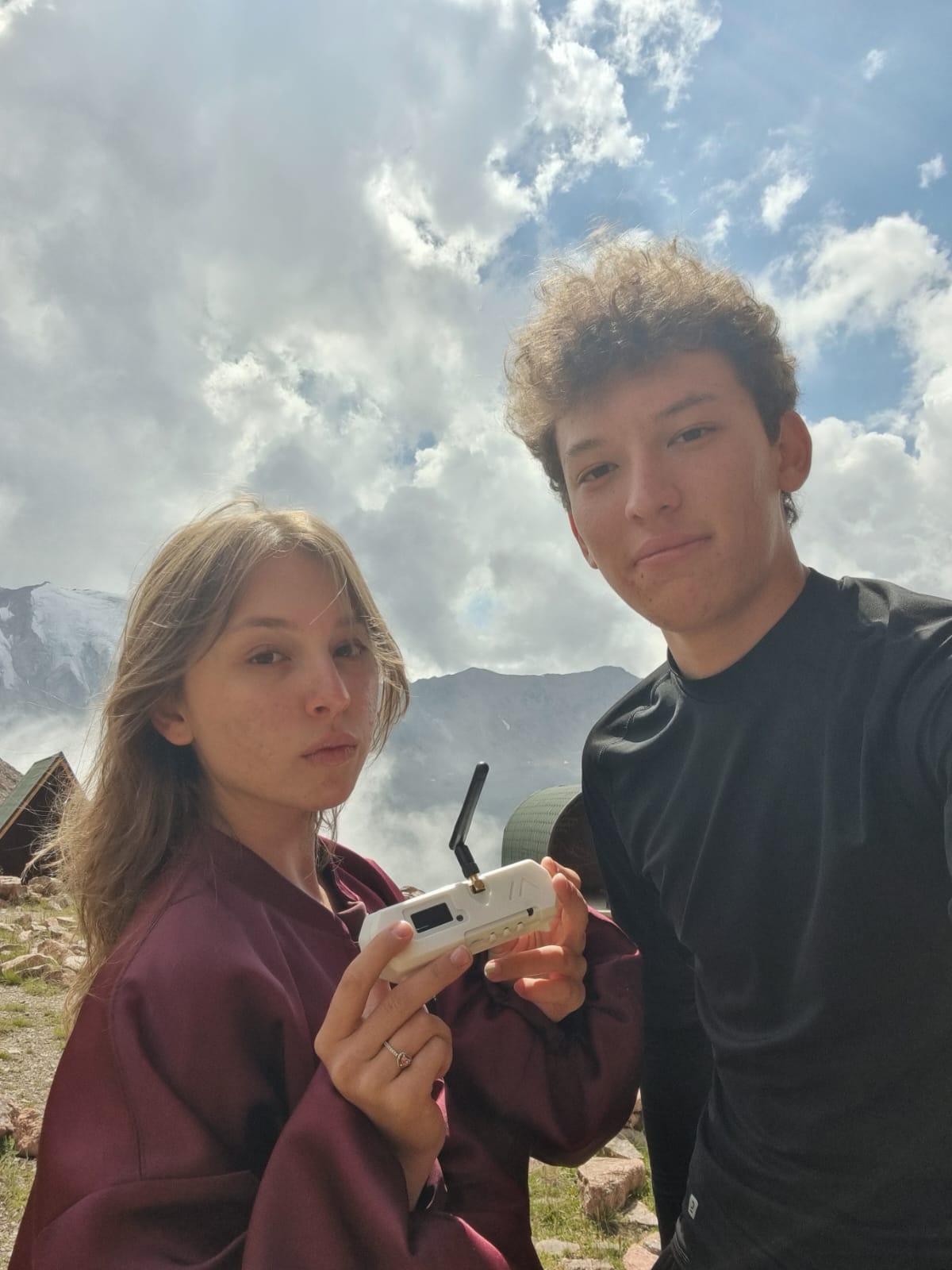
Alpine Rescue System team in the Ile Alatau mountains
15 · THE TEAM

Built in Almaty. Tested in the mountains.

Alpine Rescue System is an engineering project developed by Alisher Balbayev and Alina Akylova around one practical question: how can additional rescue information remain available when cellular connectivity cannot be assumed?

CO-DEVELOPER Alisher Balbayev

Engineering development, system architecture, hardware integration and field validation.

CO-DEVELOPER Alina Akylova

Engineering development, software integration, field testing and project validation.

CURRENT STATUS FIELD-TESTED MVP
LOCATION ILE ALATAU · KAZAKHSTAN
CORE LINK GPS + LORA + LOCAL BACKEND
NEXT STAGE CONTROLLED PILOT
ALPINE RESCUE SYSTEM OFFLINE MOUNTAIN SAFETY TECHNOLOGY ALMATY · 2026